RFID Reader Antenna Basics - The Wave® Antenna Solution
Posted by Michael Crudele on
For New Wave product information, or to order New Wave RFID antennas, visit https://www.arcantenna.com/antenna-manufacturers/newave-sensor-solution
.
RFID READER ANTENNA BASICS – THE WAVE® ANTENNA SOLUTION
Author: RJ Burkholder, Research Professor of Electromagnetics and RF at The Ohio State University
In the last several blogs I explained why the antenna is the most important part of designing a UHF RFID system (see figure below). This is because the computer software, reader, and RFID tag are fairly optimized now, and often outside the control of the system designer anyway. Performance improvements must come from the proper selection of the antenna and its deployment.

Before getting to antenna deployment in RFID system design, it was first necessary to understand the basic principles of how antennas work and how the electromagnetic field radiated by an antenna fills and penetrates a given space. The main issues are polarization, fading, gain, EIRP (effective isotropic radiated power) and diversity. A good understanding of these issues will aid the designer in selecting the type and number of antennas, and where to put them for optimum performance.
To review, we first explored the most basic characteristic of an antenna, namely, its gain. This number is defined as the directional amplification of the antenna compared with an antenna that radiates equally in all directions (isotropic). Gain is closely related to Effective Isotropic Radiated Power (EIRP). EIRP is defined as the amount of power that a theoretical isotropic antenna would emit to produce the peak power density observed in the direction of maximum antenna gain. EIRP is limited by the FCC to 36 dBm (decibels relative to a milliwatt) of RF power.
As we saw, because of this limit, it does not always help to use a high-gain antenna because the EIRP will likely be exceeded unless the RFID reader power is reduced accordingly. Next, we learned about the important characteristic of antenna polarization. Polarization defines the predominant direction of the electric field radiated or received by an antenna. It was illustrated that using a single patch-type reader antenna in a static scenario is likely to miss a significant percentage of tags simply because the polarization is misaligned. Even a circularly polarized antenna, which can detect a tag in any orientation transverse to the radiation direction, will miss tags that are oriented along the radiation direction.

Two antennas provide polarization diversity for reading an RFID tag that a single antenna is not able to read due to the tag orientation.
This introduced the most important concept of antenna diversity, which means using more than one antenna to cover a given region in order to overcome the limitations of a single antenna. Polarization misalignment is not the only limitation of using a single reader antenna. Any single antenna has nulls where the radiated field is very low. Typically, an antenna is designed so that the nulls are towards the back and sides, and the main beam is free from nulls when the antenna radiates in empty space. However, in a realistic RFID environment, there is always multipath due to reflections from the floor, ceiling, walls, and large objects that give rise to interference between direct and reflected fields. Fading occurs in regions where this interference is destructive, i.e., the fields are out of phase and tend to cancel.
Fading is overcome the same way as polarization misalignment, by using more than one antenna. The interference pattern and nulls of an antenna are very sensitive to its placement and orientation. A second antenna placed just a short distance away from the first will have a completely different pattern. This allows two or more antennas to have far better coverage of a multipath rich environment than a single antenna.
Antenna diversity is why most UHF readers have more than one antenna port. A general misunderstanding in RFID is that more antennas let you cover more area. That is true to a certain extent, but if you only have one antenna covering a given area, the read rate will suffer. For the best coverage, at least two antennas should cover any given point in the region of interest. This is illustrated below.

Diversity-rich RFID coverage zone using four patch antennas on opposite sides. Overlapping beams from different directions provide spatial diversity as well as polarization diversity.
The example above shows an effective way to cover a fairly large area using four patch antennas (up to 20 feet). The antennas can be connected to the same 4-port RFID reader. This arrangement provides polarization diversity as well by tilting the beams. However, notice that the patch antennas are not ideal for covering a specified area due to their single-beam illumination. That is why it requires at least 4 antennas.
Is it possible to design an antenna that is optimized for the type of zone coverage shown above? The answer is the Wave® antenna. The Wave® antenna is ideally suited for zone coverage with a minimum number of antennas. It makes use of distributed radiation rather than beam radiation, as shown below.
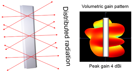
The Wave® antenna has distributed radiation from multiple points along its length. The gain pattern shows multiple beams from one antenna.
The antenna has multiple radiating elements along its length that generate multiple overlapping beams in the volume surrounding the antenna. (In fact, 5 beams have been measured from the 7-foot version of the Wave®.) Compared to the patch antenna, which is like a spotlight, the Wave® antenna is like a fluorescent light bulb. It doesn’t have the long-range and directionality of a patch antenna but provides much more uniform coverage of the area around the antenna. Furthermore, the overlapping beams of the Wave® provide all 3 polarizations, whereas a patch antenna can only provide 2 at most. This makes the Wave® ideal for item-level zone coverage of densely populated regions of RFID tagged products in warehouses, retail stores, and portals.
A single Wave® antenna could cover an entire zone, but this antenna obeys the same physical laws as any other antenna and will have nulls and polarization misalignment at certain points within its range. Therefore, a second Wave® antenna is always used in tandem with the first antenna to provide the required diversity protection, as shown below.

Wave® antennas cover the zone using only two antennas, providing natural polarization and spatial diversity.
As the figure shows, only two antennas are used to cover the entire zone, whereas at least five conventional patch antennas would be required to provide the same number of overlapping beams. It is noted that the two Wave® antennas do not need to be deployed on opposite sides of the coverage area, but can also be placed side-by-side with a small vertical offset. (Notice that the two antennas above are slightly offset in the vertical direction.)
In this and previous blogs, we have learned how to properly deploy antennas for diverse coverage of an RFID reading zone using the minimum amount of resources. Future blogs will focus on how these principles are extended to practical applications of item-level RFID in the logistics chain.
For New Wave product information, or to order New Wave RFID antennas, visit https://www.arcantenna.com/antenna-manufacturers/newave-sensor-solution